
A Velocity Sensor may look like a small component, yet its readings can shape major engineering decisions. In a motor housing, it tracks vibration as a shaft spins. In a test rig, it can reveal a change that operators might otherwise miss. For global buyers, choosing a manufacturer means looking beyond product photos and headline specifications.
Jacob Fraden, author of Handbook of Modern Sensors, explains the sensor’s basic role as converting a physical stimulus into a measurable signal. A concise paraphrase of that principle is: “Turn physical change into measurable output.” The phrase is simple. The engineering is not. Buyers should check measurement range, frequency response, sensitivity, mounting options, calibration practices, and performance across operating temperatures. A sensor that works well on a clean laboratory bench may behave differently beside a hot motor or on a loosely mounted panel.
This guide examines manufacturers through practical questions: Do their datasheets state test conditions clearly? Can they support integration, documentation, and repeat orders across regions? Are product claims supported by traceable test information? These details matter when a sensor must fit an existing system, not just a catalog description. No shortlist is perfect. Supplier capabilities and product lines change, and buyers still need to verify current specifications directly. The aim here is to help readers compare manufacturers with care, identify useful evidence, and choose a Velocity Sensor suited to the actual application—not simply the most familiar name.
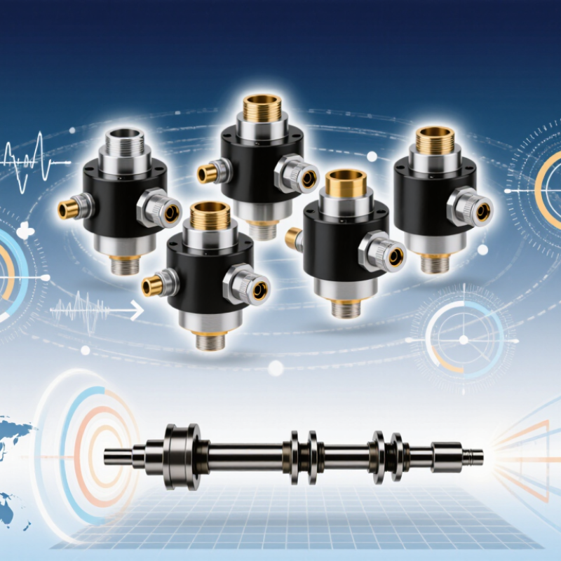
A velocity sensor measures how quickly a surface or object moves, usually expressed in millimeters per second. In machine monitoring, it captures vibration rather than simply indicating whether equipment is “on” or “off.” A technician may mount one on a bearing housing and compare readings as a motor runs. The result can help reveal imbalance, looseness, or wear—but it does not identify the fault by itself. Context matters.
Many industrial velocity sensors use electromagnetic induction. A coil moves relative to a magnet as the machine vibrates, producing a voltage related to vibration speed. The instrument converts that signal into a usable reading.
Small signal. Big consequence.
ISO 20816-3:2022 evaluates machinery vibration using RMS velocity and specifies measurement conditions across frequency ranges that can extend from 10 to 1,000 Hz for covered machine groups. This is a useful technical benchmark, not a universal pass-or-fail limit for every asset.
Mounting position, machine speed, temperature, and sensor bandwidth can all change the reading. Field data are rarely tidy; even a firm-looking number may need a second measurement and an operating-history check.
Modern velocity sensors turn motion into measurable signals, but each technology has limits. Doppler radar estimates speed from frequency shifts, making it useful when targets move through dust or light rain. Ultrasonic sensors compare sound travel times; airflow and temperature can affect their readings. Laser Doppler systems offer fine measurements, but need a clear optical path and particles to track. MEMS accelerometers can estimate velocity through integration, though small biases accumulate into drift.
The choice should follow the measurement environment, not a catalog headline. NHTSA’s Traffic Safety Facts: Speeding, 2022, recorded 12,151 speeding-related deaths in the United States. That figure is not a sensor-performance test, but it shows why speed measurement and validation matter in transport applications. For procurement, compare range, response time, repeatability, environmental limits, and calibration traceability. Ask suppliers for test conditions, not just peak accuracy. A polished specification can hide a weak fit.
Tips: Test the sensor on the real target and mounting surface. Check readings across expected speeds and temperatures. Keep a reference instrument nearby; field conditions can expose errors that a lab bench misses.
Velocity sensor manufacturers often specialize by frequency range, mounting style, and operating environment rather than offering one universal design. Some focus on industrial machinery, where sensors monitor vibration on pumps, motors, and gearboxes. Their products may provide velocity output directly, reducing extra signal conversion in monitoring systems. Match the response range and sensitivity to the machine’s actual operating conditions. Small mismatches matter.
Other manufacturers serve low-frequency monitoring, including structural and ground-motion applications. They often prioritize stable response to slow movement, low noise, and documented calibration. Field-ready models may feature sealed housings, shielded cables, and clear mounting instructions. These details can simplify installation, although site conditions may still affect readings. Cables pick up interference.
For global buyers, useful comparisons include calibration traceability, temperature range, output format, and technical support. Ask how a sensor performs near its lower frequency limit and whether mounting orientation changes its response. Test data from a similar installation can help, but it may not predict every site. Catalog specifications can look reassuring; real machinery is less tidy. A sample evaluation can reveal practical gaps before full deployment.
Compare velocity sensor manufacturers on measured performance, not headline sensitivity alone. Request frequency response, measurement range, cross-axis sensitivity, operating temperature, and uncertainty data. Check that calibration records identify the method and traceability. The ISO 16063 series provides methods for calibrating vibration and shock transducers, making it a useful reference when reviewing certificates. A neat datasheet can still hide a poor fit: mounting stiffness and cable routing may change results on a real machine.
Global support matters, too. The World Bank’s 2023 Logistics Performance Index assessed 139 economies across six areas, including logistics competence, tracking, and timeliness. It is not a supplier ranking, but it helps buyers think beyond the factory gate. Compare quoted lead times, regional calibration access, spare-part availability, and technical response hours in the destination market. Ask for a sample certificate and a written delivery estimate; vague answers are worth noting.
Tips: Test one sensor on your own equipment before placing a large order. Record the mounting method, cable length, and operating temperature, then compare readings against a reference instrument. Keep the test conditions identical. That small trial can reveal issues a polished presentation misses.
Compare published velocity specifications on a consistent basis. This chart shows exact unit conversions to millimeters per second (mm/s), a common reference unit for vibration velocity.
Conversion reference: 1 µm/s = 0.001 mm/s; 1 mm/s = 1 mm/s; 1 in/s = 25.4 mm/s; 1 m/s = 1,000 mm/s. Normalize units before comparing measurement ranges across manufacturers.
Choosing a velocity sensor supplier starts with the machine, not the catalogue. Check the measurement range, frequency response, output type, and mounting method against the actual operating conditions. A sensor fitted to a pump may face heat, oil mist, and persistent vibration. Ask for calibration records with traceability, plus stated uncertainty and test conditions. A certificate without these details is hard to assess.
Review the supplier’s technical support and documentation before ordering. Can they explain installation orientation, cable limits, and signal conditioning? ISO 20816-1:2016 provides guidance for measuring and evaluating machine vibration, including measurement conditions and locations. A capable supplier should help interpret these requirements, not just quote a part number. Test it onsite. Small details matter.
Reliability also depends on service life, spare availability, delivery consistency, and repair arrangements. The U.S. Department of Energy’s 2010 Operations & Maintenance Best Practices guide reports estimated maintenance-cost savings of 8–12% for predictive maintenance versus preventive maintenance. That figure describes maintenance programs, not sensor performance; treat it as context, not a guarantee. Ask suppliers how their calibration and support processes help keep measurements dependable over time. No checklist catches every mismatch. An early field trial can reveal one.
| Evaluation Factor | What to Compare | Questions to Ask the Supplier | Buyer Check |
|---|---|---|---|
| Measurement range | Confirm the sensor’s velocity range and whether it suits the expected vibration levels at the measurement point. Range specifications may be expressed in units such as mm/s or in/s. | What are the measurement range, overload limits, and stated conditions for those ratings? | Allow suitable headroom above the expected operating level, while ensuring the sensor can resolve the minimum signal of interest. |
| Frequency response | Check the usable frequency band and how response limits are specified, including any sensitivity variation across the band. | Is the response specified with tolerances, and are mounting conditions included in the performance data? | Match the usable band to the machine’s expected vibration frequencies and the monitoring or diagnostic task. |
| Output and system compatibility | Common options include dynamic outputs such as IEPE and conditioned outputs such as 4–20 mA. These serve different monitoring and control system requirements. | What supply, signal conditioning, cable, and input requirements apply to each output option? | Verify compatibility with the data-acquisition system, PLC, monitor, or other receiving equipment before ordering. |
| Measurement units and signal definition | Vibration velocity may be reported as RMS, peak, or peak-to-peak, depending on the sensor system and application. | How is the output scaled, and which amplitude convention and units are used? | Use consistent units and amplitude definitions across sensors, monitoring equipment, and alarm settings. |
| Mounting and installation | Review mounting method, mounting surface requirements, orientation, connector location, and cable routing. Installation can affect measured vibration. | Which mounting options are available, and what installation practices are required for the stated performance? | Confirm the sensor can be installed securely at the intended point and that the mounting method suits the machine and maintenance plan. |
| Environmental protection | Check operating temperature, ingress protection, humidity resistance, and resistance to oil, dust, or other site conditions where applicable. | Which environmental ratings apply to the complete sensor and connector assembly? | Compare documented ratings with actual site conditions; do not assume the sensor body rating also covers cable connections. |
| Hazardous-area requirements | For installations in classified hazardous locations, equipment may need certification appropriate to the location and protection method. | Can the supplier provide valid certificates and installation instructions for the required jurisdiction and zone or division? | Check that the exact model, accessories, and intended installation are covered by the required approval. |
| Accuracy and calibration | Compare sensitivity tolerance, linearity, repeatability, and any stated calibration interval or calibration service. | Is a calibration certificate supplied, and does it identify the tested unit and measurement conditions? | Review the calibration documentation and determine whether its traceability and uncertainty meet the application’s requirements. |
| Reliability and service life | Assess construction, connector and cable options, operating limits, warranty terms, and available repair or replacement support. | What warranty applies, and what repair, replacement, or technical-support process is available internationally? | Compare the documented terms and support arrangements rather than relying on general reliability claims. |
| Documentation and standards | Request clear datasheets, wiring diagrams, installation instructions, and applicable conformity or quality-system documentation. Machine vibration evaluation standards are distinct from sensor performance specifications. | Can the supplier provide current documentation for the exact model and relevant configuration? | Use the sensor specifications for instrument selection and consult the applicable machine-vibration criteria separately for evaluation limits. |
| Supply, lead time, and lifecycle | Compare quoted lead times, regional availability, product-change notifications, and availability of compatible replacement models. | How are lead times confirmed, and how much notice is given for product changes or discontinuation? | Check delivery commitments and plan for spares if downtime or long procurement cycles would affect operations. |
| Total cost of ownership | Consider the sensor price alongside required cables, signal conditioning, mounting hardware, calibration, installation, and ongoing support. | Which accessories or services are required but not included in the quoted price? | Compare complete, compatible system costs rather than sensor prices alone. |
Note: Sensor specifications and available configurations vary by model and application. Request the current datasheet and written confirmation for the exact configuration before purchase.