Custom sheet metal parts in as little as 3 days - Get a quote now!

What Is OPGW in Transmission Lines and How to Choose It?

Overhead power networks carry more than electricity. They also carry protection signals, voice communication, and operational data. That is where Opgw In Transmission Line technology becomes valuable. Optical Ground Wire combines a lightning-protection shield wire with optical fibers inside its metallic structure. It must survive wind, ice, vibration, fault current, and years of ultraviolet exposure.

“OPGW should be selected as both a communication cable and a structural conductor,” says Dr. Arun G. Phadke, a respected power-system protection specialist. This principle matters during real design work. A cable may offer enough fibers but fail the required short-circuit rating. Another option may meet electrical demands but create excessive sag after installation. Small details matter.

This guide explains how OPGW works, where it fits, and how engineers compare suitable designs. It examines fiber count, aluminum and steel areas, tensile strength, fault-current capacity, allowable sag, tower geometry, and installation tension. It also considers splice boxes, optical loss, grounding, and maintenance access. The most expensive choice is not always the strongest one.

Field conditions can expose weaknesses that a clean datasheet hides. A mountain route may need stronger mechanical performance. A coastal corridor may require better corrosion resistance. Existing towers may also have limited spare capacity. That changes the decision.

There is no universal OPGW specification. Careful selection is essential. Sometimes, the first design is wrong. Reviewing assumptions early can prevent failures, delays, and unnecessary replacement costs.

What Is OPGW in Transmission Lines and How to Choose It?

What Is OPGW and What Role Does It Play in Transmission Lines?

OPGW, or Optical Ground Wire, combines two critical functions in one overhead conductor. It shields transmission lines from lightning while carrying optical fibers for protection, control, and voice communication. Installed at the tower’s highest point, it can transmit relay signals within milliseconds. Its aluminum and steel construction must also withstand fault current, wind, ice, vibration, and installation tension.

It is not magic. Mechanical performance still matters.

The International Energy Agency’s Electricity Grids and Secure Energy Transitions report estimates that over 80 million kilometers of grids must be added or refurbished globally by 2040. This expansion increases demand for reliable communication paths beside energized circuits.

Single-mode fibers often follow ITU-T G.652 specifications, with attenuation near 0.22 dB/km at 1550 nanometers. Selection should match span length, short-circuit current, sag limits, fiber count, and local weather data. A higher fiber count is not always better. Extra weight can increase tower loading and sag.

Tips:

Check the utility’s existing tower drawings before choosing OPGW. Confirm the required short-circuit rating and maximum allowable sag. Review ice and wind records, not only average weather. Field crews often discover that connector planning was overlooked. Keep spare fibers for future protection upgrades. I would also question every “standard” choice, because a familiar design may fit one corridor poorly.

How Is OPGW Designed and What Are Its Main Components?

OPGW, or Optical Ground Wire, combines two functions in one overhead cable. It shields transmission lines from lightning and carries fiber-optic communication signals. Its design begins with the required electrical, mechanical, and communication performance. Engineers consider span length, fault current, wind, ice, temperature, and installation tension. They also check tower geometry and available clearance. Small assumptions can create expensive problems later.

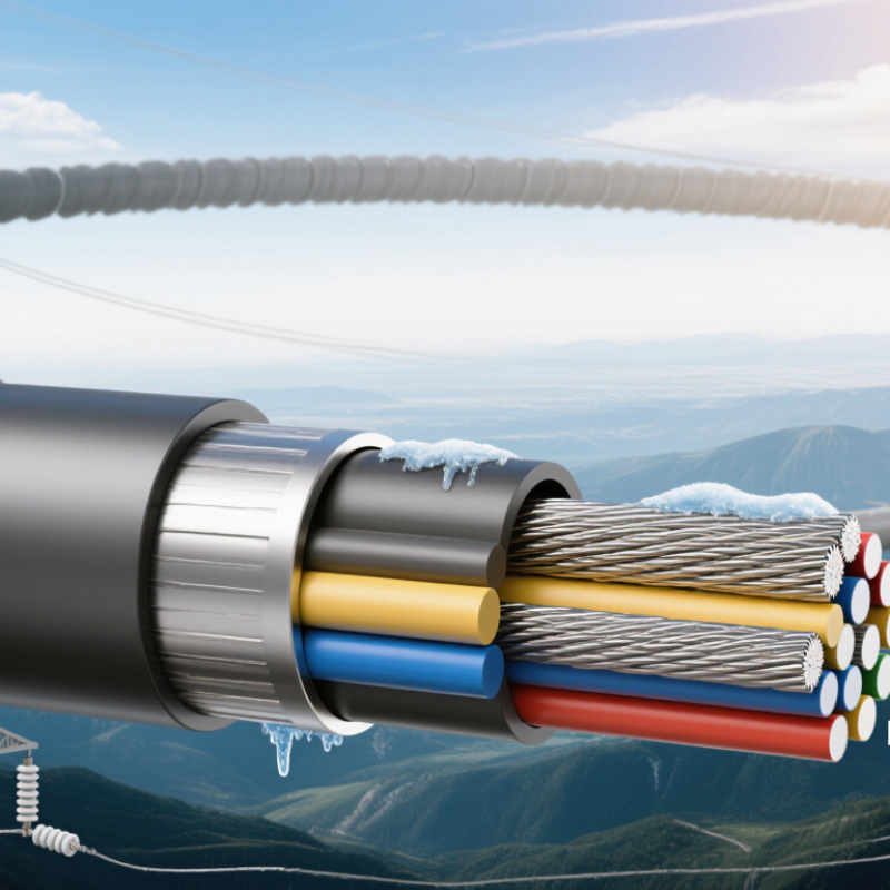
The central strength member usually contains steel or aluminum-coated steel wires. These wires provide tensile strength and help the cable withstand short-circuit heating. Around the center, one or more stainless-steel tubes protect the optical fibers. The tubes may contain loose fibers and a water-blocking compound. This arrangement allows limited fiber movement during temperature changes. The outer wires commonly use aluminum alloy or aluminum-clad steel. Their arrangement controls conductivity, weight, diameter, and resistance to corrosion.

The fiber count depends on network capacity, protection needs, and future expansion. Too few fibers restrict upgrades, while excessive capacity can increase size and cost. A practical selection compares rated tensile strength, fiber attenuation, thermal short-circuit rating, sag, and installation limits. Testing should follow recognized cable and transmission-line standards. Field teams must inspect handling, pulling tension, bending radius, and grounding connections. Design software helps, but it does not replace site measurements. Not every design is ideal. A cable that performs well electrically may still be difficult to install or maintain.

What Is OPGW in Transmission Lines and How to Choose It? - How Is OPGW Designed and What Are Its Main Components?

Category Parameter or Component Typical Data or Construction Selection and Design Relevance
Basic Definition OPGW meaning Optical Ground Wire; a composite overhead earth wire containing optical fibers. It combines lightning shielding, fault-current conduction, and high-speed communication in one transmission-line component.
Installation position Normally installed at the top of transmission towers as a shield wire. The tower arrangement and shield angle must be checked to maintain adequate protection against direct lightning strikes.
Primary functions Lightning shielding, short-circuit current path, and optical telecommunications. The selected design must satisfy both electrical grounding requirements and mechanical overhead-line requirements.
Common reference standards IEC 60794-4, IEEE 1138, and applicable national overhead-line standards. The project specification should identify the governing standard, test methods, environmental conditions, and acceptance criteria.
Main Components Optical fibers Usually single-mode fibers, commonly compliant with ITU-T G.652.D or G.655 requirements. Choose fiber type according to transmission distance, wavelength, dispersion requirements, and network architecture.
Fiber count Common configurations include 12, 24, 36, 48, 72, and higher fiber counts. Provide enough fibers for current services, protection, maintenance, and planned network expansion.
Optical unit A stainless-steel tube, aluminum tube, or stranded optical unit surrounding the fibers. The unit protects fibers from moisture, crushing, vibration, thermal effects, and installation strain.
Central tube or buffer structure Fibers are loosely contained to provide excess length and reduce tensile stress transfer. Loose-tube construction helps maintain optical performance during temperature changes and mechanical loading.
Metallic strength members Aluminum-clad steel, aluminum alloy, galvanized steel, or combinations of these wires. The metallic layers provide tensile strength, electrical conductivity, thermal capacity, and resistance to environmental loads.
Water-blocking materials Water-blocking gel, dry water-blocking tape, or water-swellable yarns. These materials limit longitudinal water migration and help protect the fibers over the service life.
Protective outer surface The outer stranded metallic layer forms the weather-resistant and electrically conductive surface. Surface construction affects corrosion resistance, allowable current, vibration behavior, and compatibility with fittings.
Key Electrical Data Rated tensile strength Project-specific; often selected from several kilonewtons to tens of kilonewtons. It must withstand everyday tension, wind, ice, installation loads, and the required safety factors.
Short-circuit current rating Specified in kA for a defined fault duration, commonly 0.5 s or 1.0 s depending on the system study. Select the cross-sectional area and material combination based on fault current, duration, initial temperature, and permissible final temperature.
DC resistance Specified in ohms per kilometer at a reference temperature, usually 20 °C. Lower resistance improves fault-current performance and reduces voltage rise between tower grounding points.
Lightning current capability Determined by metallic area, material, strand construction, and thermal limits. Verify the design against the expected lightning environment and tower shielding requirements.
Induced-current and magnetic effects Depend on line geometry, phase currents, grounding arrangement, and OPGW impedance. System studies may be required where parallel circuits or high continuous currents create significant induction.
Optical attenuation Common single-mode fiber limits are approximately 0.35 dB/km at 1310 nm and 0.22 dB/km at 1550 nm, subject to the specified fiber grade. Use the guaranteed project value, including splice, connector, aging, and repair margins, for link-budget calculations.
Key Mechanical Data Overall diameter Common transmission-line designs are approximately 8–20 mm in diameter, although larger designs are possible. Diameter affects mass, wind area, ice loading, sag, fittings, and tower-head clearance.
Unit mass Often approximately 250–1,000 kg/km, depending on diameter, metallic area, and fiber configuration. Check tower loading, foundation reactions, stringing equipment, and installation limitations.
Elastic modulus A calculated or tested composite value based on the strand materials and construction. Required for sag-tension calculations and should be consistent with the selected installation method.
Coefficient of thermal expansion A composite property influenced by the proportions and arrangement of steel and aluminum-based wires. Use the manufacturer’s verified value to predict sag at minimum, everyday, and maximum operating temperatures.
Bending performance Must meet specified minimum bending radius and fiber strain limits during handling and installation. Improper sheave diameter, pulling tension, or sharp bends can cause permanent optical attenuation.
Vibration resistance Designed for aeolian vibration, galloping, and subspan motion according to the line environment. Assess the need for vibration dampers and ensure the selected fittings match the OPGW construction.
How to Choose OPGW 1. Determine fiber capacity Define active fibers, protection fibers, spare fibers, and future expansion requirements. Avoid selecting fiber count only from present demand; replacement or additional installation may be difficult after energization.
2. Check fault-current duty Use the maximum prospective fault current and clearing time from the protection study. The OPGW must remain mechanically and electrically suitable after the thermal fault event.
3. Perform sag-tension analysis Consider span length, ruling span, temperature range, wind pressure, ice thickness, and installation tension. Confirm clearance to conductors, towers, roads, buildings, vegetation, and other infrastructure.
4. Match tower and fittings Verify suspension clamps, dead-end assemblies, bonding leads, splice closures, and grounding connections. Fittings must be compatible with the OPGW diameter, strand construction, rated tensile strength, and short-circuit requirements.
5. Evaluate environment Review wind, ice, temperature, altitude, pollution, salt exposure, corrosion, and lightning conditions. Material selection and corrosion protection should reflect the actual route environment rather than a generic catalogue value.
6. Confirm optical performance Check attenuation, chromatic dispersion, polarization characteristics, fiber strain, splice compatibility, and optical return loss. The complete link budget should include cable length, splices, connectors, repair reserves, and the required operating margin.
Inspection and Testing Routine production tests Dimensional inspection, fiber attenuation measurement, tensile-related checks, and electrical resistance verification. Confirm that every manufactured drum meets the approved technical specification.
Type tests Mechanical, environmental, thermal, vibration, optical, and short-circuit performance tests as applicable. Type-test evidence demonstrates that the design is suitable for the specified service conditions.
Installation inspection Check drum condition, pulling tension, bending radius, sag, clamps, grounding, and splice closures. Installation records help identify mechanical or optical damage before commissioning.
Optical acceptance test Use an optical time-domain reflectometer and light-source/power-meter measurements at the specified wavelengths. Compare measured results with the approved link budget and investigate abnormal splice loss or reflective events.

Note: Typical ranges are for general engineering reference only. Final OPGW dimensions, materials, ratings, and test limits must be selected from the project design conditions and the approved technical specification.

What Are the Key Benefits and Applications of OPGW?

OPGW combines a shield wire with optical fibers above transmission conductors. It protects lines from lightning. It also carries high-speed communication traffic. Utilities use it for SCADA, relay protection, voice systems, and synchrophasor data. The fiber path can support fault location and remote substation control.

The benefit is practical. During a fault, fast data may help operators isolate the affected section.

After storms, communication remains available when separate telecom routes fail.

The need is growing. The International Energy Agency reported in Electricity Grids and Secure Energy Transitions (2023) that annual grid investment must exceed 600 billion dollars by 2030. The U.S. Department of Energy’s National Transmission Needs Study (2023) estimated that transmission capacity may need to expand 60% by 2030. OPGW can support that expansion, especially on new high-voltage corridors and rebuilt lines.

Selection should match fiber count, short-circuit current, span length, sag, wind, ice, and installation tension. IEC 60794-4-10 provides relevant optical ground-wire requirements and test guidance.

A common mistake is choosing by fiber count alone. The weak point may be thermal performance or joint protection. Field experience matters.

A spreadsheet cannot fully predict every tower, splice, or storm.

How to Select the Right OPGW for a Transmission Project?

Selecting the right OPGW begins with the transmission line, not the fiber count. OPGW combines a lightning shield wire with optical communication fibers. Its design must match the tower geometry, span length, and grounding system.

Start by defining the communication requirement. Count present fibers, then reserve fibers for future protection, monitoring, or network expansion. Choose single-mode fibers when long-distance, low-loss communication is required. Check fiber attenuation, splice performance, and operating temperature. More fibers are not always better. Extra fiber tubes can increase diameter, weight, and installation difficulty.

Mechanical and electrical data require equal attention. Compare rated tensile strength with maximum span, wind pressure, ice loading, and conductor sag. Confirm the short-circuit current and fault duration with the protection engineer. The OPGW must safely carry fault energy while remaining within its temperature limit. Review applicable requirements, such as IEC 60794 and IEEE 1138, alongside local grid rules. Hardware compatibility matters too. Check dead-end fittings, suspension clamps, bending radius, and tower attachment points before ordering.

Field experience shows that early drawings often hide practical problems. A technically strong OPGW may still fail if its diameter conflicts with existing fittings. I have seen fiber capacity receive more attention than fault-current calculations. That is an expensive imbalance. Recheck every assumption with line survey data and manufacturer test reports. Selection is rarely perfect on the first attempt. Allow room for correction.

What Installation and Performance Factors Should Be Considered?

What Is OPGW in Transmission Lines and How to Choose It?

What Installation and Performance Factors Should Be Considered?

OPGW combines overhead grounding protection with optical fiber communication. It usually sits at the tower peak, where lightning exposure is highest. Choosing it requires more than checking fiber count. The cable must match span length, tower strength, fault current, and local weather. Ice and wind loads can change sag significantly. Short-circuit heating also affects the metallic design.

Installation quality strongly influences long-term performance. Confirm the designed sag-tension values before stringing. Use suitable pulling tension and keep the cable away from rough surfaces. Respect the specified bending radius, especially near suspension and termination fittings. Fiber damage can remain invisible during construction. It may appear later as higher attenuation. That is costly to discover.

Grounding and bonding deserve close attention. Poor connections can create dangerous voltage differences during faults. Check every fitting, clamp, and tower connection against the engineering drawings. After installation, perform visual inspections, continuity checks, and OTDR testing on each fiber. Record attenuation, splice loss, and cable identification carefully. Experienced crews also inspect drum handling and storage conditions. Water, crushed sections, or careless braking can compromise a new cable.

Field conditions are rarely perfect. A planned route may contain tighter access, unexpected ice, or inaccurate tower records. That is where installation plans need revision, not stubborn repetition. One practical weakness is relying only on factory data. Actual performance also depends on fittings, workmanship, and seasonal loading. Small errors can become expensive faults.

What Is OPGW in Transmission Lines and How to Choose It?

The chart compares representative OPGW designs by fiber count, approximate mass, and rated tensile strength. During selection, engineers should also verify span length, wind and ice loading, sag-tension behavior, short-circuit thermal capacity, allowable installation tension, minimum bending radius, and compatibility with existing tower hardware.

Values are representative engineering figures for commonly used OPGW configurations, not a product specification. Final selection must be based on the project span, environmental loads, fault-current duration, optical requirements, and the applicable transmission-line standards.