What Is an MPO Cable and How Does It Work?
An MPO Cable is a multi-fiber assembly built around a connector that carries several optical fibers in one interface. In a data center, that can mean connecting a trunk cable to a cassette or switch port without handling each fiber separately. The result is a compact connection for high-density fiber links. Neat, but not effortless.
Inside the connector, fibers sit in precise rows and align with matching fibers at the opposite end. Depending on the optical design, several fibers may transmit and receive data in parallel. The connector’s key, pin configuration, and fiber polarity help determine whether those paths meet correctly. A mismatch can leave a link dark, even when the cable appears firmly connected. Small details matter.
This guide explains what an MPO Cable is, how its fibers and connector work, and where MPO assemblies are commonly used. It also covers practical choices such as fiber count, polarity, connector type, and compatibility with cassettes or transceivers. These specifications can vary between systems, so a familiar connector shape is not enough to confirm a match. Clean end faces and careful inspection are important, too; dust can affect performance through a connection that looks fine to the eye. The technology is efficient, though setup can be less simple than it first appears. Understanding the parts makes planning, installation, and troubleshooting more reliable.
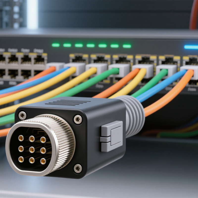
MPO Cable: Definition and Core Purpose
An MPO cable is a fiber-optic cable assembly that uses MPO connectors to join multiple fibers in one compact connection. MPO means “multi-fiber push-on.” A connector can hold several fiber ends in a single ferrule, so one cable can carry parallel optical signals. Common configurations include 8, 12, or 24 fibers, though the exact count depends on the application.
Its core purpose is to make high-density fiber links practical. In a data center, an MPO trunk can connect patch panels or optical equipment while taking up less rack space than many separate duplex cables. It can also reduce the number of individual connections technicians must make during installation. That saves space. It may save time, too.
The details matter. Fiber count, connector gender, polarity, and single-mode or multimode type must match the equipment and link design. A cable that physically fits may still transmit incorrectly if its polarity is wrong. I would not treat MPO as a simple plug-and-play shortcut; labeling and end-to-end testing are easy to underestimate. For example, checking the fiber map before connecting a trunk can prevent hours of tracing crossed channels later.
Key Components of an MPO Cable Assembly
An MPO cable assembly carries multiple optical fibers through a single connector. Its key parts work together to keep each fiber aligned and protected. Inside the connector, an MT ferrule holds the fiber ends in a precise row. Guide pins and alignment holes help mate the ferrule with another connector. Even a small mismatch can weaken the optical connection.
The connector housing surrounds the ferrule and provides a surface for handling and latching. A key on the housing helps control orientation, while the cable jacket protects the fibers from everyday bending and abrasion. Some assemblies also include a fanout, which separates the bundled fibers into individual connectors. Polarity—the path each fiber takes from one end to the other—depends on the assembly design. It can be easy to overlook.
Tips: Check the connector type, fiber count, and polarity before installation. Keep end faces clean, and inspect them with suitable equipment. Small details matter. A cable may look correct but still fail to link properly if its components or orientation do not match the system.
How MPO Cables Carry Multiple Fiber Signals
An MPO cable carries several optical fibers inside one compact connector. Its polished endface holds a row of fiber cores, each aligned with a matching core in the port. Light travels down each fiber independently. In parallel-optics links, a transceiver sends and receives multiple lanes at the same time, rather than combining every signal onto one fiber. For example, IEEE 802.3’s 400GBASE-SR8 specification uses eight transmit fibers and eight receive fibers. That makes a 16-fiber MPO connection useful for high-capacity links across a data center rack. Fast, but alignment matters.
The need for dense links is growing. Synergy Research Group reported that the number of hyperscale data centers worldwide passed 1,000 in 2024. MPO cabling helps organize many optical paths in limited space, but the connector does not create bandwidth by itself; compatible transceivers, fiber type, and lane mapping must all match. One detail is easy to overlook: transmit and receive positions need correct polarity at both ends. A reversed array can leave a link dark, even when the cable looks intact. Dust is another practical problem. A small particle on one core may weaken that lane while its neighbors still work. MPO systems are efficient, though troubleshooting can feel less obvious than with a single-fiber connector.
MPO Connector Types and Polarity Configurations
MPO connectors bring multiple fibers into one compact interface, but the connector’s shape does not tell you how those fibers are mapped. Common configurations include 8-, 12-, and 16-fiber layouts. Some MPO connectors use alignment pins; the pinned connector mates with an unpinned one. Key orientation also matters. A connector’s key can face up or down, changing how its fiber positions line up with the adapter.
Polarity describes the path each fiber takes from one end of a link to the other. Type A keeps fiber positions straight, while Type B reverses their order. Type C swaps each adjacent fiber pair. Small changes, big effects. These patterns help connect transmit and receive channels correctly, especially in parallel optical systems. A polarity mismatch may leave a link dark or cause channels to land on the wrong fibers.
Before installation, check the connector type, pin arrangement, key orientation, and polarity method at both ends. Then compare them with the transceiver and cabling plan. MPO end faces are small and easy to contaminate, so inspect and clean them with tools made for fiber connectors. Don’t rely on cable labels alone; labels can be unclear, and documentation may not reflect later changes. That check is easy to skip. It is also where a seemingly sound link can go wrong.
What Is an MPO Cable and How Does It Work?
Common fiber-position counts in MPO connector formats
MPO cables carry multiple fibers in a single connector, with common configurations containing 8, 12, 16, 24, or 32 fiber positions. Polarity describes how transmit and receive fibers map between cable ends: Type A is straight-through, Type B reverses the array, and Type C swaps adjacent fiber pairs. The correct polarity depends on the equipment and link design.
Common Applications and Selection Factors
MPO cables bundle multiple optical fibers into one connector, making them useful where space and port density matter. In data centers, they commonly link switches, servers, and patch panels through trunk cables or cassette modules. Some parallel-optics systems use MPO connections to transmit several channels at once. Telecom rooms may also use them to simplify high-fiber-count routes. The connector saves panel space, but a mistake in fiber mapping can disrupt several links at once.
Choose the cable for the equipment at both ends. Check fiber type, such as multimode or single-mode, and confirm the required core count, polarity, and connector configuration. Male and female ends must match the mating hardware. Review insertion-loss limits and cable length, especially for longer routes or cascaded connections. A tight bend behind a rack can degrade performance, even when the cable looks intact. Compatibility details can feel tedious; they are worth checking before ordering.
Tips: Confirm the polarity map and connector pin configuration with the equipment documentation. Label both ends before installation, then inspect and clean the end faces. Leave enough slack for servicing, but avoid coils that exceed the cable’s bend-radius guidance. A quick visual check helps, but it cannot replace optical testing.
