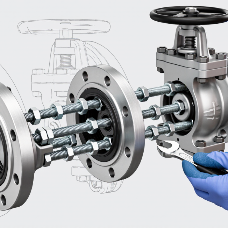
| Primary Function | Creates an adjustable flanged connection between a valve, pipe, pump, meter, or other equipment item. | Use it where equipment may need to be removed without cutting the pipeline or moving large pipe sections. |
| How It Works | A telescopic body changes the face-to-face length, while tie rods transfer axial forces and maintain the assembled connection. | Set the joint within its specified adjustment range; do not use it as a substitute for pipe alignment or permanent structural support. |
| Common Applications | Water transmission, water treatment, pumping stations, industrial process lines, and buried or above-ground flanged pipework. | Confirm that the application, fluid, pressure class, temperature, and installation environment are compatible with the joint design. |
| Nominal Size Range | Commonly available from approximately DN50 to DN2000, depending on the design and applicable standard. | Match the nominal diameter, flange drilling, outside diameter, and connection standard to the adjoining equipment. |
| Adjustment Allowance | Many designs provide an installation adjustment of roughly ±25 mm to ±50 mm, although the exact range varies by size and manufacturer design. | Verify the actual minimum, maximum, and nominal face-to-face dimensions before ordering and setting the pipework. |
| Pressure Rating | Typical water-service ratings include PN10, PN16, and PN25; some systems use ASME pressure classes such as Class 150. | Select a pressure rating equal to or greater than the system design pressure, including foreseeable surge conditions. |
| Body Material | Common options include ductile iron, carbon steel, and stainless steel. | Consider fluid chemistry, corrosion exposure, operating temperature, mechanical loads, and coating requirements. |
| Flange Compatibility | Compatibility depends on nominal size, pressure class, bolt-hole pattern, flange outside diameter, and gasket seating arrangement. | Check all mating dimensions; nominal size alone does not guarantee interchangeability between standards. |
| Gasket Selection | Elastomeric gaskets such as EPDM or NBR are commonly used, subject to the fluid and temperature. | Use a gasket rated for the service medium, pressure, and temperature. Replace damaged, hardened, or previously compressed gaskets. |
| Tie Rods and Fasteners | Tie rods and nuts are commonly supplied in carbon steel or stainless steel, with corrosion protection selected for the environment. | Confirm rod quantity, diameter, material, coating, and tightening requirements. Never remove restraints while the line is pressurized. |
| Installation Position | Can be installed in horizontal or vertical pipework when the joint and support arrangement are suitable. | Provide independent supports or anchors as required. The joint should not carry unplanned pipe weight or bending loads. |
| Pre-Installation Checks | Inspect the joint, flange faces, gasket surfaces, fasteners, coating, and adjustment range before assembly. | Remove dirt and protective transport materials from sealing surfaces, and confirm that the pipeline is depressurized and properly aligned. |
| Alignment Requirement | Dismantling joints accommodate axial length adjustment but generally do not correct major angular or lateral misalignment. | Correct pipe alignment and support conditions before tightening the joint. |
| Bolt Tightening | Bolts should be tightened gradually in a diagonally opposite or cross-pattern sequence. | Use the specified torque or tightening procedure. Uneven tightening can cause gasket leakage or flange distortion. |
| Pressure Testing | Hydrostatic testing is commonly performed with clean water at the project-specified test pressure. | Vent trapped air, increase pressure gradually, inspect for leakage, and follow the governing pipeline or project standard. |
| Routine Inspection | Visual checks typically cover leakage, corrosion, coating damage, loose nuts, gasket extrusion, and unusual movement. | Inspect during scheduled pipeline maintenance and after abnormal pressure events, vibration, flooding, or nearby excavation. |
| Replacement Indicators | Persistent leakage, severe corrosion, damaged threads, distorted flanges, cracked components, or loss of adjustment capability. | Isolate and depressurize the line before repair or replacement. Investigate the underlying cause rather than only replacing the gasket. |