
10 Best Industrial EMC Solutions for Global Buyers
Industrial equipment rarely operates in isolation. A variable-speed drive can send noise along a cable tray, while a nearby sensor struggles to deliver stable readings. For global buyers, choosing an Industrial EMC Solution means looking beyond a product catalogue. The real question is how well its filters, shielding, grounding, and installation guidance fit the equipment and site. Small details matter.
EMC engineer Henry W. Ott is widely respected for practical guidance on electromagnetic compatibility. A useful paraphrase of his design philosophy is: “Control interference at its source, and manage its path before it reaches sensitive circuits.” This is a paraphrase, not a verified verbatim quotation. It points to a useful habit: ask suppliers how they test, document, and support their solutions. Request clear test conditions, installation instructions, and evidence relevant to the intended application. A result without context can mislead.
This guide reviews ten industrial EMC options for buyers comparing suppliers across markets. It considers typical use cases, technical strengths, selection questions, and practical trade-offs. Not every solution fits every plant. A filter that performs well in a laboratory may need careful cable routing and bonding in a crowded control cabinet. That gap deserves attention. The comparisons are a starting point, not a substitute for engineering review or project-specific testing. Even experienced teams miss things. Recheck the assumptions before purchase.
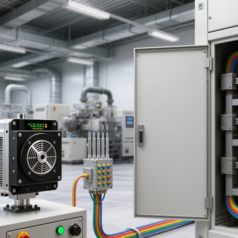
Industrial EMC Fundamentals: IEC 61000-6-2 Immunity and 61000-6-4 Emissions
Industrial EMC design has two sides: equipment must tolerate interference and avoid disturbing nearby systems. IEC 61000-6-2:2016 sets generic immunity requirements for industrial environments, while IEC 61000-6-4:2018 addresses emissions. These standards apply when a more specific product or product-family standard does not. The IEC 61000-6-2 test matrix includes radiated RF immunity levels of 10 V/m across applicable frequency bands. It also specifies tests for electrostatic discharge, electrical fast transients, and surges. Exact levels depend on the port and test conditions.
For emissions, IEC 61000-6-4 defines limits and measurement methods for industrial equipment. A drive cabinet may pass in a quiet lab yet create problems beside long sensor cables or shared power lines. Installation details matter. Cable routing, bonding, enclosure seams, and filter placement can change real-world performance. Treat compliance testing as a design check, not a guarantee that every site will behave identically.
Tips: Check the applicable IEC edition and port requirements before choosing test levels. Keep power and signal cables separated, and bond cabinet doors with short, low-impedance straps. Record cable lengths and grounding points during testing; these details are easy to overlook.
10 Best Industrial EMC Solutions for Global Buyers - Industrial EMC Fundamentals: IEC 61000-6-2 Immunity and 61000-6-4 Emissions
This comparison covers ten commonly used EMC solution approaches for industrial equipment. IEC 61000-6-2 addresses immunity in industrial environments, while IEC 61000-6-4 addresses emissions in those environments when a relevant product or product-family EMC standard does not apply. The required tests and limits depend on the equipment, ports, installation, and applicable standards.
| No. | EMC Solution | Primary Purpose | Relevant EMC Tests or Topics | Typical Industrial Use | Selection and Design Considerations |
|---|---|---|---|---|---|
| 1 | Conducted EMI input filters | Reduce high-frequency noise conducted between equipment and its power supply network. | Conducted emissions; IEC 61000-6-4 context; filter performance may also support immunity. | Control cabinets, motor drives, power supplies, and automated machinery. | Choose for the supply voltage, current, frequency, and expected noise spectrum. Follow the filter maker’s wiring and bonding guidance; poor installation can reduce effectiveness. |
| 2 | Shielded enclosures and conductive gaskets | Limit radiated electromagnetic energy entering or leaving an equipment enclosure. | Radiated RF immunity testing to IEC 61000-4-3; radiated emissions assessment. | Control units, measurement equipment, industrial computers, and sensitive electronics. | Maintain electrical continuity at seams, doors, and removable panels. Cable openings and ventilation apertures can compromise shielding if not designed appropriately. |
| 3 | Cable shields and 360-degree terminations | Reduce coupling of RF disturbances onto signal and control cables and help contain cable-borne noise. | Radiated and conducted RF immunity; emissions from connected cables. | Encoder, sensor, fieldbus, and motor cables in electrically noisy installations. | Select cable construction for the signal and environment. Termination method and bonding depend on the equipment design, installation, and frequency range; avoid long, unbonded shield pigtails where high-frequency performance is required. |
| 4 | Surge protective devices | Limit transient overvoltages caused by events such as switching operations or lightning-related surges. | Surge immunity testing to IEC 61000-4-5. | AC and DC power inputs, outdoor equipment, and long cable runs between buildings or exposed locations. | Coordinate the protective device with the supply system, expected exposure, upstream protection, and equipment withstand. Short, correctly routed connections are important for performance. |
| 5 | ESD protection and discharge-path design | Protect accessible surfaces and electronic interfaces from electrostatic discharge. | ESD immunity testing to IEC 61000-4-2. | Operator-accessible panels, touch displays, connectors, and maintenance interfaces. | Consider contact and air discharge points, enclosure materials, connector layout, and the route by which discharge current returns to the chassis. Protection components must suit the interface signal requirements. |
| 6 | EFT and burst suppression | Improve resilience to fast transient bursts associated with switching inductive loads and relay contacts. | Electrical fast transient/burst immunity testing to IEC 61000-4-4. | Control and signal ports near contactors, relays, solenoids, or switching equipment. | Use suitable suppression at the disturbance source or interface, and review cable routing and port protection. Required test conditions vary by port and equipment standard. |
| 7 | Signal-line filtering and interface protection | Reduce unwanted RF and transient energy entering signal, data, and control circuits while preserving intended signals. | Conducted RF immunity to IEC 61000-4-6; EFT and surge tests may also apply to relevant ports. | Analog sensor inputs, digital I/O, communication ports, and long field wiring. | Match the filter and protection approach to signal bandwidth, data rate, impedance, and isolation needs. Validate the complete port with its intended cable and termination. |
| 8 | Bonding and grounding architecture | Provide controlled, low-impedance connections between conductive parts and reduce unwanted voltage differences. | Supports immunity and emissions performance; relevant to ESD, RF, and transient current paths. | Machine frames, cabinets, cable entry plates, drive systems, and interconnected control panels. | Plan protective earthing and EMC bonding according to applicable electrical safety rules and the equipment design. Use short, direct high-frequency bonding paths where required; grounding is not a substitute for port protection. |
| 9 | Power-supply isolation and transient conditioning | Reduce the transfer of disturbances between the supply network and sensitive equipment. | Voltage dips and interruptions to IEC 61000-4-11 where applicable; surge and conducted disturbance considerations. | Automation controllers, instrumentation, and process-control equipment with defined power-quality needs. | Determine whether isolation, filtering, ride-through, or an uninterruptible supply is needed from the disturbance profile and required operating behavior. These approaches do not replace required EMC testing. |
| 10 | Pre-compliance EMC testing and design verification | Identify emissions and immunity weaknesses early, before formal conformity assessment. | Tests may include IEC 61000-4-2, -4-3, -4-4, -4-5, -4-6, -4-8, and -4-11, as applicable; emissions methods depend on the relevant standard. | New product development, design changes, and troubleshooting of industrial installations. | Test representative configurations, cable lengths, operating modes, and port setups. Pre-compliance results help guide design but do not by themselves establish conformity to IEC 61000-6-2 or IEC 61000-6-4. |
Important: IEC 61000-6-2 and IEC 61000-6-4 are generic EMC standards for industrial environments. A product-specific or product-family standard may take precedence. Confirm the applicable edition, test levels, performance criteria, and market requirements for the equipment before selecting or validating an EMC solution.