
Custom sheet metal parts in as little as 3 days - Get a quote now!

What Is a BESS Connector and How Does It Work?

A Bess Connector is a purpose-built electrical interface that links battery modules, racks, and power-conversion equipment. It may look like a compact plug or a bolted terminal, but its role is substantial. It carries current, supports dependable contact, and helps keep connections organized during installation and maintenance. In a battery energy storage system, small details matter. A loose joint can create heat; a poorly matched connector can complicate servicing. The right design depends on current, voltage, conductor size, enclosure conditions, and the system’s operating demands.

This guide explains what a BEss Connector is, how it works, and which features deserve close attention. We will look at contact surfaces, insulation, locking mechanisms, and the path electricity takes through a connection. We will also consider practical issues, such as checking labels before mating connectors and inspecting for discoloration or damaged seals. These details are useful, though no single checklist fits every installation. The exact selection and inspection process should follow the equipment manufacturer’s documentation and review by qualified personnel. A verified quotation and name from a BESS connector specialist were not provided, so I will not invent an expert attribution. That gap matters. Reliable technical guidance should distinguish sourced statements from editorial explanation, especially when discussing equipment that carries significant electrical energy.
What Is a BESS Connector and How Does It Work?

What Is a BESS Connector?

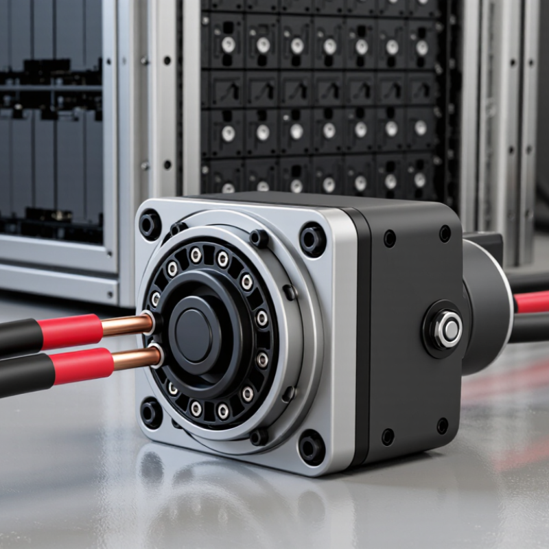
A BESS connector is an insulated electrical interface that links battery modules or racks to busbars, converters, or neighboring units. It carries high current while keeping live contacts protected from accidental touch. Some designs also include smaller pins for temperature sensing or interlock signals. The connector does not store or convert energy. It makes the electrical path between system components secure and serviceable.

Its details matter. Contact material, locking force, cable size, and insulation rating affect heat, vibration resistance, and safe operation. A poor connection can develop extra resistance and create a hot spot; even a small temperature rise deserves attention. The IEA’s 2024 Batteries and Secure Energy Transitions report records about 42 GW of battery storage additions worldwide in 2023. That rapid growth makes dependable connections increasingly important, although the figure measures storage deployment, not connector failures. A connector should be selected for the system’s voltage, current, environment, and maintenance plan. Dust, moisture, and repeated handling can change real-world performance. A datasheet helps, but it cannot replace careful installation and inspection. There is no single connector suited to every BESS.

Where a BESS Connector Fits in an Energy Storage System

Inside a battery energy storage system, a BESS connector sits at an electrical boundary. It links battery modules to a rack, or connects racks to a DC collection bus. From there, power can flow to the power conversion system, which changes DC electricity into AC for site use or the grid. The exact arrangement varies with system design.

Some connectors carry high current; smaller ones may carry monitoring or interlock signals. Both matter. A loose power connection can create heat, while a poor signal connection may interrupt monitoring. Installers check voltage and current ratings, cable size, polarity, and locking features against the equipment specifications. They also inspect the fit and cable routing. Small details count.

Not glamorous. Still essential. A connector does not store energy or control charging by itself. It provides a defined, serviceable link within a larger electrical path. Placement also affects access during inspection and maintenance, so designers need to consider clearance, vibration, and temperature near the battery racks. Specifications alone may not reveal every site condition. An on-site check can catch awkward bends or limited service space before they become recurring problems.

What Is a BESS Connector and How Does It Work? - Where a BESS Connector Fits in an Energy Storage System

System Location or Aspect What It Does How the Connector Fits In Key Considerations
Battery cells and modules Cells store energy electrochemically and are assembled into modules to provide the required voltage and capacity. Electrical connections join cells within a module and link modules in the battery assembly. These connections may use busbars, welded joints, or separable connectors, depending on the design. Connection methods and serviceability vary by battery design. Cell-level connections are not necessarily plug-in connectors.
Battery racks Racks group battery modules into larger units that can be monitored and connected as part of the storage system. Power connectors or other approved terminations carry direct current (DC) between modules, racks, and the next electrical stage. Connector voltage, current capacity, polarity, and compatibility must match the equipment design and installation requirements.
DC collection and distribution DC cabling and distribution equipment bring power from battery racks toward the power conversion system. A BESS power connector provides a defined electrical interface between compatible cables and equipment, helping establish a secure, low-resistance current path. Some systems use a DC combiner or other distribution equipment; the exact arrangement depends on system architecture.
Power conversion system (PCS) The PCS converts battery DC power to AC power for discharge and converts incoming AC power to DC during charging. Connectors and cable terminations link the battery-side DC circuits to the PCS in accordance with the system design. A BESS connector does not perform DC-to-AC conversion; that function belongs to the PCS.
Energy management and control Control equipment coordinates charging, discharging, monitoring, and system operation. Separate low-voltage signal or communication connections may carry measurement, status, or control signals. They are distinct from high-power connections. Communication interfaces and protocols vary. Power connectors should not be treated as communication connectors.
Connector construction A connector assembly typically includes conductive contacts, an insulating housing, and a method of securing the connection. The contacts conduct current; the housing helps maintain electrical separation; and the mating or locking mechanism helps keep the connection engaged. Features such as touch protection, keying, sealing, or a locking mechanism depend on the connector and application.
Making and maintaining a connection A compatible connector pair is aligned, mated, and secured according to its instructions. Correct mating establishes the intended electrical path. Disconnecting, where permitted, separates that path for approved service procedures. Connectors must be used within their rated conditions. Installation and maintenance should follow the equipment manufacturer’s instructions and applicable electrical codes.
Protection and safe servicing System protection and operating procedures help reduce electrical and thermal hazards. Some designs may include interlocks or touch-safe features, but a connector alone does not make a battery system safe to service. Isolate the equipment and verify the absence of hazardous voltage using the required procedures before service. Do not connect or disconnect energized equipment unless it is specifically designed and approved for that operation.
Typical energy path During discharge, stored energy moves from the battery toward the electrical load or grid; during charging, energy flows in the reverse direction. Battery connections → DC distribution → PCS → AC equipment. Connectors provide interfaces at selected points along this path. The number, type, and location of connectors vary with the BESS layout and equipment configuration.

Key Components and Interfaces of a BESS Connector

A BESS connector links battery modules or racks to the system’s power path. Its main contacts carry direct current to a busbar or cable leading toward power-conversion equipment. Contact size, material, and surface finish affect resistance and heat. Even a small rise in resistance can create noticeable warmth under sustained load. Fit matters.

The housing keeps contacts aligned and helps prevent accidental access. Insulating barriers, seals, and a locking feature support safe, stable connections in cabinets where dust, vibration, or moisture may be present. Some designs include a high-voltage interlock loop. This low-voltage circuit can signal that a connector is not fully engaged. It does not replace isolation procedures or inspection.

Interfaces vary by system. A connector may use keyed power poles to preserve polarity, while separate pins carry temperature or interlock signals. Communication links, such as CAN or RS-485, are often routed through distinct low-voltage connectors rather than the main power interface. Check rated voltage, current, cable size, mating compatibility, and environmental limits against the system design. A connector that fits physically may still be unsuitable. Details are easy to overlook.

How a BESS Connector Transfers Power and Signals

A BESS connector is the physical interface between battery modules, the power conversion system, and control equipment. Its power contacts carry high-current direct current from the battery racks toward the inverter. A separate set of smaller contacts can carry signals for voltage, temperature, and status monitoring. Small pins. Big responsibility.

During operation, the power path moves energy; the signal path helps equipment coordinate. A battery management system can report a rising module temperature through signal wiring, while an interlock circuit can prevent operation if a connector is not fully seated. The connector does not regulate power by itself. It provides a controlled connection, and the surrounding electronics decide how the system responds. Pin assignments and communication protocols vary by design, so compatibility must be verified rather than assumed.

The International Energy Agency’s Batteries and Secure Energy Transitions report (2024) says battery storage capacity in its Net Zero Emissions scenario rises sixfold to 1,200 GW by 2030. That growth makes reliable interfaces increasingly important across large installations. In practice, technicians inspect contact surfaces, locking features, and cable strain relief; a tiny amount of looseness can create heat under heavy load. Yet a clean wiring diagram cannot show every real-world issue. Dust, vibration, and rushed maintenance deserve more attention than they often get.

How a BESS Connector Transfers Power and Signals

Power contacts carry high current between the battery system and its equipment. Separate signal contacts can communicate an interlock state, helping control when power transfer is permitted. This simplified sequence is illustrative, not a connector specification.

Common BESS Connector Types and Their Applications

BESS connectors link battery racks, power-conversion equipment, and control systems. High-current DC connectors join modules or racks where quick, secure connections matter. Bolted busbar terminals suit fixed, high-current paths inside cabinets. Smaller signal connectors carry temperature, voltage, and communication data. Each has a different job. A connector that fits electrically may still be wrong for the enclosure, cable size, or service conditions.

Applications vary with system design. Rack-level plug-in connectors can simplify replacement, while busbars handle larger currents between cabinets and inverters. Control connectors link battery management systems to sensors and protection equipment. The International Energy Agency’s Batteries and Secure Energy Transitions (2024) says global battery storage capacity must reach 1,200 GW by 2030 in its net-zero pathway, about six times the 2023 level. That scale makes dependable connections essential, though the report does not prescribe one connector type. Real installations are less tidy than diagrams.

Tips: Check rated voltage, current, temperature, polarity, and touch protection against the equipment specifications. Inspect contact surfaces and verify torque on bolted joints. Do not mix connector families based on appearance alone; small differences can cause poor contact or overheating. A careful compatibility check takes time, but replacing a hot connector takes longer.

Article Source: